Friday, February 1, 2013

Problems with the Soundtraxx Tsunami AT1000

I have been doing quite a few decoder installs lately, with the decoder of choice being the Tsunami AT1000.  These are great decoders and easy to install. However they can be a bit long and make the job harder when it comes to finding space for them in the loco.  One problem I have now encountered on 3 different decoders is a power drop in and out.  The symptoms are, during the loco running it will stop and start constantly as though you have dirty wheels.  After a long process of fault finding and trying new things I finally sent the thing back to Soundtraxx.  They repaired the first one under warranty, however there are terms and conditions to that.  They informed me there was a soldering joint issue.  2 months later I helped a friend with an install to a 44 class.  Again the same problem,  so I tried another decoder I had to see if it was OK, again for a third time the same problem.  So I contacted Soundtraxx to see what this soldering fix may be and if I could do this myself?  After a detailed email explaining the solution I decided to send them both back for repair as I attempt it at my own peril.  A friend sent me an email from rail page the other day with someone having what sounded like the same problem, so I thought I would give you all the solution as it seems to be a reoccurring problem.


The black arrow shows the resistor which is the issue. If this resistor is not sitting completely flat this is the cause. On mine one was sitting proud less than 1mm on one end, the second was completely vertical! Keep in mind Soundtraxx will repair free under warranty ($25 shipping!!) or you can have a go yourself, but unless you are extremely good at soldering and have a steady hand don't do it!
 

Another problem I had the other day was a short in the loco....  This loco had been working fault free for months then all of a sudden was creating a short circuit.  Upon removal of the body this is what I faced.  The front pickup wires had melted together! I'm not sure what caused this but it was an easy fix, just replace the pick ups and your away. 

The melted wiring.

Wednesday, January 2, 2013

Having a Crack!

So I have purchased one of those static grass applicators from eBay.....
Below are the results.  The guy I purchased it from was Aussie Scenics, it was $40 with free post.  It uses 2 D cell batteries which makes it very portable.  It was easy to use and it gave me a couple of tickles when I wasn't paying atttention.  Oh and read the instructions, because when it says to short the dispenser with the ground pin after use, do so cause the shit of a thing strores a pretty good charge, even when the batteries are removed!

 The area near the coal stage.

 Around Boggabilla station and platform.

The yellow and red clumps are flowers/weeds from Noch.  They are pre made all you need to do is glue them down.

 The other side of the station.


 The longer grass clumps are also from Noch.

An overall view.  I think I might do it again with a dryer and longer grass to immitae spinifex grass with a green undergrowth.

Tuesday, January 1, 2013

Light up!

After reading Darren's Christmas post on his problems with his DCC shorting when the trains are travelling through his points when they are thrown in the wrong direction. I thought I would show my application of light bulbs which are wired in series with the frog that I found on the Allen Gartnier Web site for DCC.


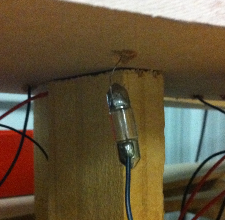
The Tortoise machine showing the light bulb wired onto the common terminal of the PCB.  The other side of the bulb will be connected to the Dropper for the frog.  The Red and Black wires you see are the power to the Tortoise motor.  Not shown is the wiring to the N/O and N/C contacts.  They will go on the the 2 terminals between the Red wire and the light bulb black wire.

Here you see the Tortoise and light bulb in place.
The blue arrows are pointing to the common wire from the Tortoise to the frog.


With the point in the correct direction there is no light and the train works fine.

With the point thrown in the wrong direction the bulb glows, yet you see the headlight still working on the CPH.  This means that the DCC has not gone out on a fault and the train will continue through the point.  Unless it derails!


The bulb in place, soldered to the dropper from the frog section of the point.
A dodgy schematic to show the connections.

Sunday, September 30, 2012

Perfect Timing!

Iwas gifted a couple of BCW's from a mate after he purchased some Eureka ones.  I didn't feel like spending the time on them to get them operational as I have a pack myself and there is no need for any more.  I decided to put one to use as lineside detail.... but I had no pictures or immedate thoughts.

After reading Rod's post on "What to do with those old wagons?" Some pictures were borrowed (hope that's OK Rob?) and the idea I was formed!  Because this will eventually end up on my layout I decided to deviate from the pictures on Rod's  Blog in regards to the scenery and chose my own path.


The donor wagon.


The Door removed and reglued in the open position.
At this stage it has also had a new coat of paint and the weathering applied.


Again prior to construction.
I had another plan in mind. Since I accidently glued down my show and tell plan for the Armidale convention, I decided to make a diaorama.  This way when the convention is over I can fit it in place on my layout where the scenery has not yet been started.


The Diaorama as of this evening.  I thought it might be best not to show you the completed project.
That way if you go to the convention it won't be as nice. 


View from a lower angle.


Last minute changes saw me add this small section of handlaid track.   I thought I should add some rails, it looks nice and adds to the scene.  Unfortunatly It will be pulled up when added to the layout.
The other problem now is that I am so happy with the handlaid track I now want it for my layout.....SHIT!  Perhaps one day??


A closer view of the track.
As I said it is not yet complete as I have a few more ideas I want to implement.

Sunday, September 16, 2012

Take 3!

You may recall a few blogs back that I had built a Timber road overpass out of Styrene.  Well Mark 1 sold to a friend, Mark 2  went to eBay and Mark 3 made it to the layout.  Below are a few shots of the installation of the bridge, of course it is not completed, I haven't put up a post in 6 months so I thought I had better come up with something.....


After the bridge was painted, it was test fitted to ensure that once plastering had been completed it wouldn't require too much bastardization to get it to fit.


Looking along the single lane dirt road after the plastering had been completed.


The view from the North.


The first of the dirt has gone down to get an idea of how it will look.


Laying of the dirt and Ballast has been completed.


The view in the opposite direction.


A final close up.

Wednesday, March 28, 2012

Improvements.....

As I said in the last post I was a little unhappy with the colour of these structures. So I decided to give them a dry brush with some grey to tone them down a bit. Here is the end result.


I think the bridge looks a little more weathered in the timber now.


The yards now look no where near as dark as they were in the last post.


Something extra, these cattle grids were measured at "Bungulla" and made from styrene. This won't be their final location, it was just a good spot for a photo.


Monday, March 26, 2012

Painting things.

The sun was shining and time was on my side, so what better to do than paint some of the structures I had previously built.


This is a 10ft stock underpass? I saw this structure on the Tenterfield to Wallangarra line the other week when we went for a drive. I took a lot of pictures and some measurements to knock this one up from styrene, it's not too hard if you take lots of photos and have some timber measurements for reference.


The view of the other wing wall. You will notice that the one on the left has rail where the one on the right has timber poles. It seems that the bridge I saw may have had the timber poles fail and the rail was a repair job. The other difference on the real structure was that the timber was full lengths on the side with the poles, the side with the rail was reconstructured from used sleepers. I was a bit too lazy to copy this.


Opposite side of the bridge.


The stock ramp now with a coat of paint. You may remember the post I did on this one earlier in the year.


I think it may need a bit more of a grayish dry brush, it still looks a bit dark.